
Created by Jason Wright (jpw97) and Jeremy Blum (jeb373) for Cornell University’s ECE4760 course
Introduction
We designed and built a system to automatically orient a solar panel for maximum efficiency, record data, and safely charge batteries. Using a GPS module and magnetometer, the HelioWatcher allows the user to place the system anywhere in the world without any calibration. The HelioWatcher then calculates what the sun’s current location is and orients the panel to the appropriate angle. It also utilizes a quadrature of light-detecting diodes to correct for short-term light obstruction, such as clouds or shade. Data is logged to a computer to allow the user to visualize the efficiency gains and power consumption in real time or after the data collection has occured.
MultiMedia & External Information
- Checkout the HelioWatcher photoset on Flickr
- Download the HelioWatcher Source Code from GitHub
- Download the HelioWatcher 3D Design files from Thingiverse
High level design
Project Rationale
Solar panels are frequently used for power generation in off-grid areas, such as for solar charge stations for electric vehicles. In order to maximize efficiency of these charge stations, solar panels must be oriented depending on both the time of day and the current season. Called active solar trackers, most of these systems are expensive, require precise calibration, and are designed only for massive arrays of solar panels. We wanted to implement a system that was small scale, low-cost, easy to use, and that would provide information about efficiency to teach new solar operators about solar panel operation.
Background Math
Many solar trackers implement movement based on either a pre-determined algorithm or by adjusting position according to light detection. We sought to utilize a combination of both, to leverage the guaranteed accuracy of a geospatial algorithm while correcting for local or short-term changes, such as cloud cover or shade.
We first explored an algorithm produced by Ibrahim Reda and Afshin Andreas for the National Renewable Energy Laboratory to determine the current solar position using GPS data. This algorithm calculates azimuth and zenith angles with an accuracy of 0.0003 degrees, and is supposedly valid for centuries. The algorithm is incredibly complex, far too complicated to summarize in brief, but it basically uses the Julian day, the Earth’s heliocentric longitude and latitude, the nutation in longitude and obliquity caused by the moon, and many other factors to produce an extremely accurate result.
We ended up using a slightly simpler algorithm developed by Prof. Richard B. Goldstein of Providence College which uses only trigonometry and best fitting for the current decade to produce a fairly accurate result. This algorithm was easier to implement and work with, and had sample code available that was compatible with AVR.
To monitor light detection, we originally developed a quadrature of LEDs to monitor the difference in ambient light along the compass axes. In practice, we realized that shade from the solar panel would make the results from such a quadrature less useful, so we mounted the LEDs directly onto the sides of the panel itself, and monitored difference in ambient light along the axes of movement of the solar panel itself. This allows us to use voltage differences between two different LEDs to create an “adjustment factor” to consider alongside the pre-calculated optimal angles.

Logical Structure
The system operates as a shell interface, allowing the user to send a number of commands to the HelioWatcher over UART with optional arguments. These commands are detailed below, but most are used for operation of individual components of the system, for testing or calibration purposes. The shell also allows the user to switch to an “automatic” mode, which triggers a series of actions intended to track the sun if the HelioWatcher were left in place over a long period of time. There is also a “data logging” mode that is identical to automatic mode but limits traffic over UART to only commands relevant to data logging.
The “data logging” mode has the following basic structure:
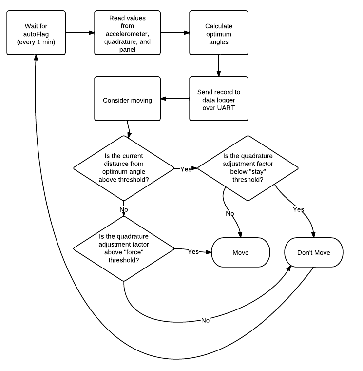
Included in our project is also an automatic data logger that connects to the HelioWatcher through a serial command, puts the system in data logging mode, visualizes the data, and stores it in a CSV file. This data could then be incorporating into further data visualization software or used for statistical purposes to track the efficiency of a solar panel over time.
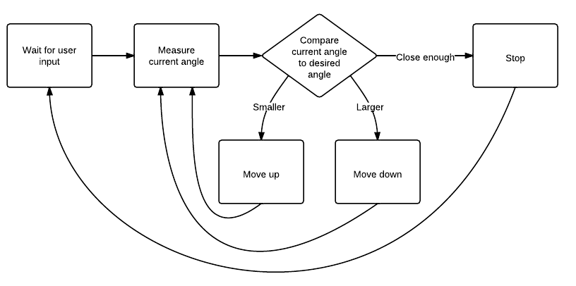
Movement, in general, is handled by iterating motor commands for small steps and continuously checking the relevant sensor (accelerometer or magnetometer) to update position, as shown in the following flow chart:
Program/hardware design
Hardware Details
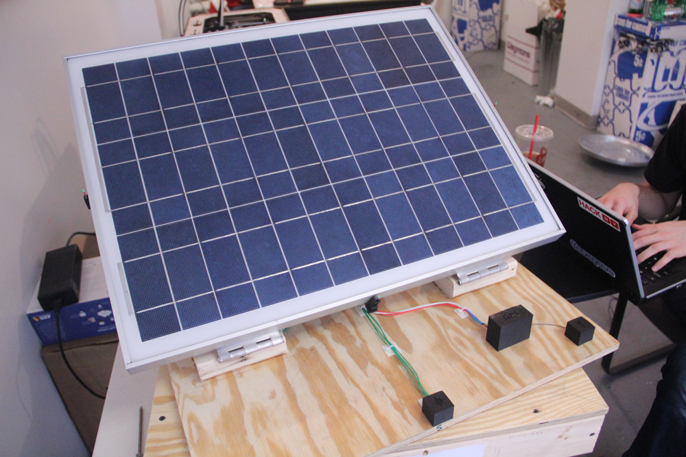
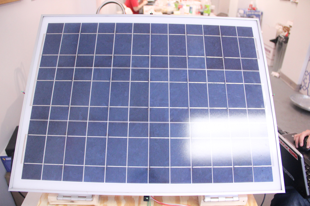
Shown above is the complete HelioWatcher System. It consists of a rotating platform (with electronics hidden underneath), a hinged panel, 4 light-sensing LEDs, a magnetometer, a GPS module, an Accelerometer, 2 stepper motors for facilitating movement, and an MightyBoard ATMega-based motherboard for embedded control.
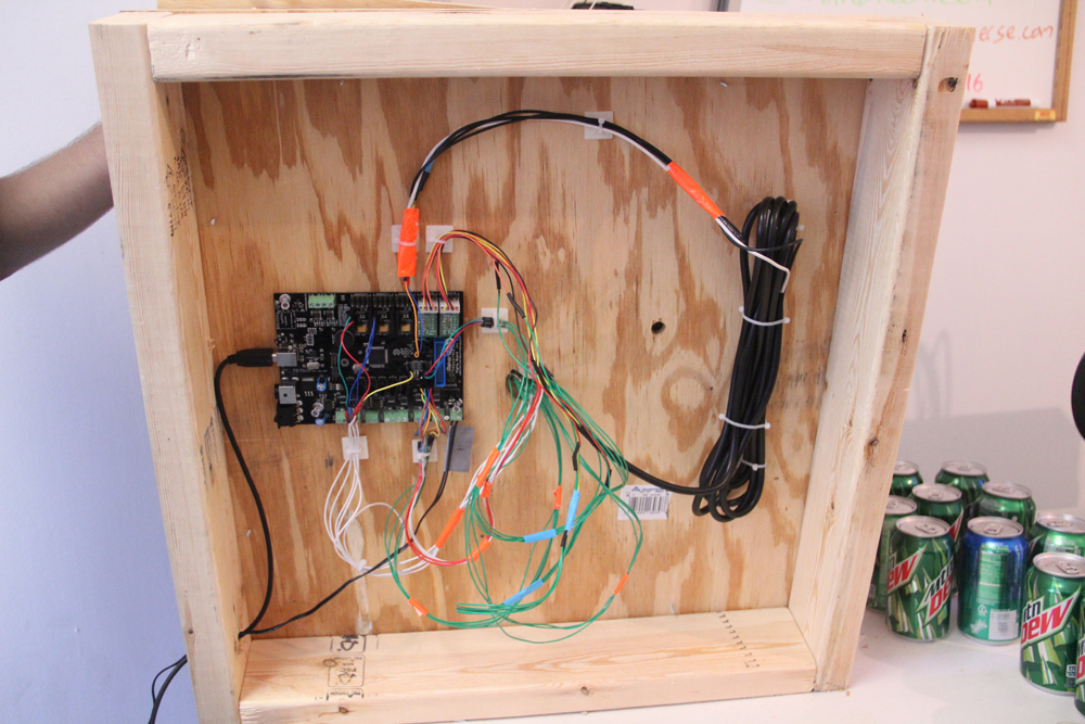
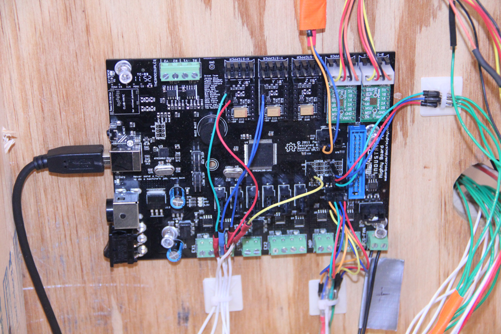
At the heart of the system is the MakerBot MightyBoard, a motherboard that was designed by Jeremy during his time working at MakerBot Industries. It was designed to control the MakerBot Replicator, a 3D printer which was coincidentally used to print the plastic components used in the construction of the HelioWatcher. The MightyBoard is well suited for controlling the HelioWatcher for a number of reasons:
- Jeremy already owned one which he uses for MakerBot software development
- It can easily control stepper motors, and even has the circuitry built in to set stepper current values for adjusting torque
- It has lots of breakout pins which make it easy to interface external devices such as the UART GPS and the I2C magnetometer that we used for the HelioWatcher
- It implements an ATMega1280, which has lots of memory for potentially storing the large lookup tables that we use for calculating optimal panel positions
- It has an onboard serial to USB conversion, using an ATMega 8U2
- It is easily expandble in the future, with circuitry for adding thermocouples, additional sensors, etc
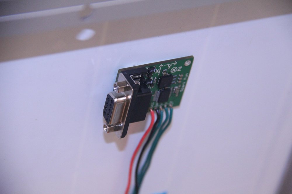
A 3D accelerometer, mounted to the rear of the panel, feeds back an analog value to the MightyBoard, proportional to the tilt of the panel. An equation is used to translate this from voltage values to tilt in degrees.
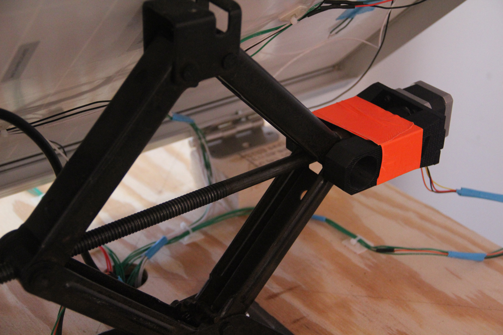
The panel is titled up and down by actuating a car jack. A car jack was chosen to actuate the panel tilt, because it easily allows rotational motion to be turned into vertical motion. A bracket & collar were 3D-printed to attach a stepper motor directly to the shaft of the car jack. By turning the stepper motor, the jack can be moved up and down, thus changing the tilt of the panel.
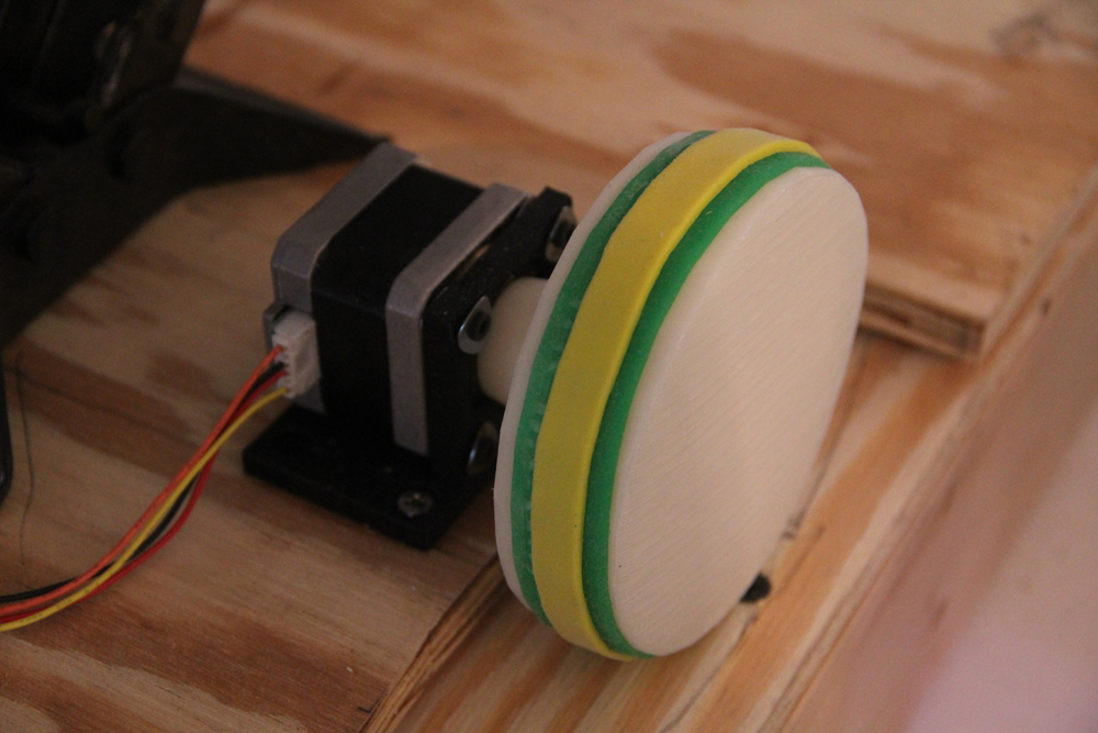
To rotate the panel, the entire system was mounted upon a lazy susan. A stepper motor mounted to the top board turns a 3D-printed wheel to advance the HelioWatcher around the circumference of the lazy susan. The wheel was wrapped in wrist bands to help with traction, and we found that applying weight to the rear of the top board also helps to ensure good traction.
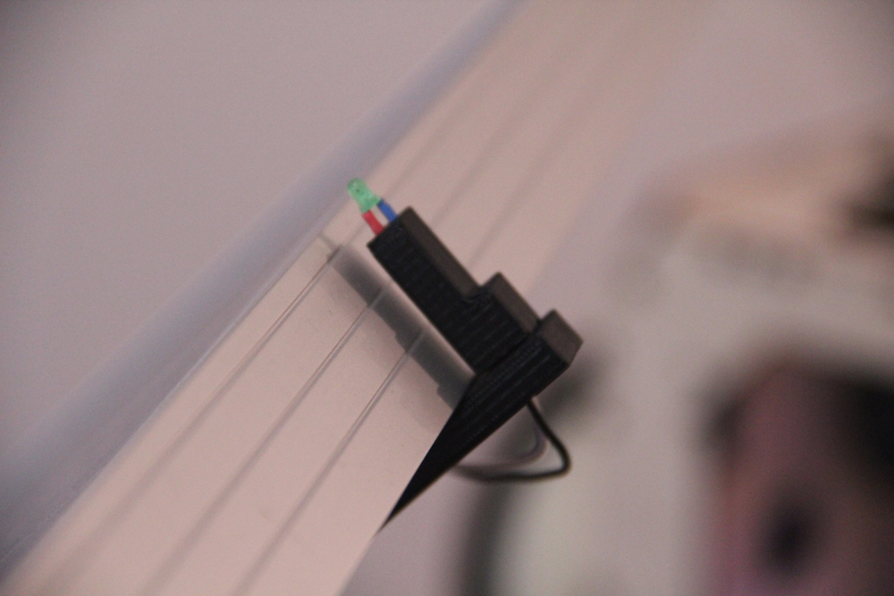
While sun tracking was made possible using GPS data, a quadrature of LEDs was also implemented as analog inputs to direct directional sunlight. By analyzing the amount of light hitting each LED, on each side of the panel, it is possible to determine when more light is coming from a direction that GPS might not predict, during cloud cover, for example.
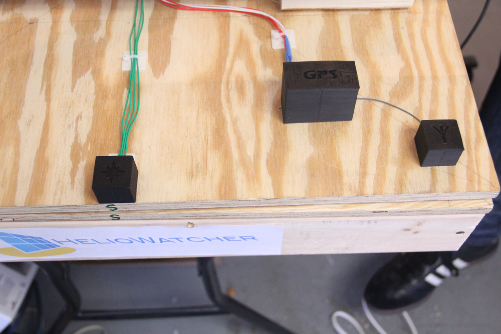
Mounted to the front the HelioWatcher, in protective 3D-printed enclosures are a GPS module + antenna and a magnetometer. The GPS module connects to available public-access GPS satellites and determines the panel current location, as well as the UTC time. This information is reported back to the MightyBoard via UART1, and can be processed with our optimization algorithm to determine where the panel should be pointed at any given time or location in the world.
The magnetometer was originally implemented to serve as a compass for determining the panel’s orientation and for making a closed loop feedback system to assist in rotating the panel. However, we quickly discovered that magnetic interference made getting repeatable compass values almost impossible. Luckily, this compass module included a Z-axis measurement, which we had originally planned to not use. Instead of using the traditional X and Y axis to calculat direction, we used the magnetic interference to our advantage. We installed evenly spaced ferrous screws around the circumference of the rotating board, and aligned them underneath the magnetometer. As the top board rotates, the Z-axis reading spikes dramatically upon running over one of these screws. In this way, we essentially turned the magnetometer into a rotation encoder. Basically, it’s rotating stud finder!
Embedded Program Details
As mentioned previously, the base of the HelioWatcher’s user interface is a shell. The system loops on an fgets command to read user input as a command with an optional argument. The available shell commands, with argument syntax, are:
accel -- read accelerometer value (void)

angle -- go to angle (degrees)

angletoscrew -- convert angle to screw (degrees)

auto -- go into auto mode (void) **can't leave this

ccw -- go to nearest CCW screw (void)

compass -- get compass rotation (void) **DEPRECATED

cw -- go to nearest CW screw (void)

data -- go into data logging mode (void) **can't leave this

date -- display the current date (void)

down -- move down (ms)

gotoopt -- move to optimal position (void) **must run opt first

gps -- read GPS values (void)

help -- list HelioWatcher shell functions

left -- move left (ms)

opt -- get optimal positioning info based on current GPS data (void) **must run gps first

panel -- display the panel voltage (void)

quad -- view quadrature values (void)

record -- print string that would be sent to data logger (void)

right -- move right (ms)

rot -- go to rot (degrees) **DEPRECATED

screw -- go to arbitrary screw (screw num)

setday -- set UTC day (int)

sethour -- set UTC hour (int)

setmin -- set UTC min (int)

setmonth -- set UTC month (int)

setsec -- set UTC sec (int)

setyear -- set UTC year (int)

time -- display the current time (void)

torch -- orient based on quadrature demo (sensitivity 0-100) **can't leave this

up -- move up (ms)
In addition, several protocols are used to interface with the various components of the HelioWatcher.
Stepper Motors — BotStep 17 drivers were included on the MightyBoard, which allow easy control of stepper motors by sending square waves over digital IO pins. The frequency of the square wave controls the speed of the motor. The torque of the motor, which is proportional to the current flowing through the electromagnets that adjust the stepper motor’s orientation, is controlled by a digital potentiometer that is addressable using I2C. Because the MightyBoard has multiple stepper motor drivers on the same board, each with the same address, a software I2C implementation was necessary to send I2C commands over other IO pins. A “bit-banging” approach is utilized, meaning that software itself controls timing, levels, and synchronization, without automatic hardware demodulation. We used AVRlib’s implementation of software I2C for this purpose, and wrote functions to rotate each stepper in a certain direction for any given duration.
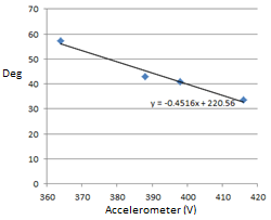
Accelerometer — The SparkFun IC that we used has three lines with x, y, and z values with voltages proportional to the gravitational field. Because only the x value was of interest to us, that line is connected directly to an ADC pin and read periodically. To convert the accelerometer values to (pitch) angles, we measured a few data points and fit a linear equation, as shown below.
Magnetometer — As mentioned previously, magnetic interference and inaccuracy prevented us from using this as a compass, as we originally intended. We instead just measured the magnetic field in the z-axis, which spikes whenever the magnetometer passes over a screw. This data is transmitted over hardware I2C, and is read periodically whenever the HelioWatcher needs to rotate. The base value of the magnetic field in the z-direction and the threshold necessary to consider the magnetometer close enough to a screw are stored separately and were determined through experimentation.
GPS Module — This device communicates over UART, continuously sending formatted GPS sentences of various formats. Because we needed UART to communicate with the user, the Joerg Wunsch avr-libc UART library that we’ve used all semester was modified to create a second file object for the GPS module’s UART stream, with a different bandwidth (4800 baud) and separate TX and RX lines.
GPS sentences are defined by a specification developed by the National Marine Electronics Association (NMEA). There are many different sentence types available, but we chose to use GGA, which provides essential fix data, including a UTC time string that we used to seed our real-time clock. We considered polling the GPS periodically to get time data, but decided to implement a timer-based RTC instead due to lower power consumption and to ensure that the time would be at least fairly accurate if the GPS connection was lost.
GGA sentences have the following structure:
$GPGGA,123519,4807.038,N,01131.000,E,1,08,0.9,545.4,M,46.9,M,,*47
Where:
GGA — Global Positioning System Fix Data
123519 — Fix taken at 12:35:19 UTC
4807.038,N — Latitude 48 deg 07.038′ N
01131.000,E — Longitude 11 deg 31.000′ E
1 — Fix quality: 0 = invalid
1 = GPS fix (SPS)
2 = DGPS fix
3 = PPS fix
4 = Real Time Kinematic
5 = Float RTK
6 = estimated (dead reckoning) (2.3 feature)
7 = Manual input mode
8 = Simulation mode
08 — Number of satellites being tracked
0.9 — Horizontal dilution of position
545.4,M — Altitude, Meters, above mean sea level
46.9,M — Height of geoid (mean sea level) above WGS84
ellipsoid
(empty field) — time in seconds since last DGPS update
(empty field) — DGPS station ID number
*47 — the checksum data, always begins with *
The NMEAP library by David Howard was used to parse GGA sentences, in particular, to extract latitude, longitude, altitude, and UTC time. The parser also provides additional useful information, like the number of active satellites, that allow us to determine the accuracy of received data.
Real Time Clock — We implemented a software RTC using the 16-bit Timer/Counter1, configured to interrupt every 1 ms with an ISR that increments UTC time component values appropriately. Although this configuration results in a high frequency of interrupts, the lower prescaler used (8) is less prone to error over time, which is significant because our system is designed to operate continuously for a very long time.
Solar Positioning Algorithm — The goal of solar positioning algorithms is to take location and time data and convert it to an azimuth & zenith angle that describes the position of the sun in the sky. We explored a few different options, including an incredibly complex algorithm written by an NREL researcher that is supposedly accurate through year 6000. We ended up using a more light-weight algorithm by Prof. Richard B. Goldstein of Providence College that is fairly accurate for at least the next decade or so.
Quadrature — The LEDs produce a small amount of voltage when light shines on them. This voltage is read by dedicated ADC pins, and some math is done to convert the voltage differences along each axis into a “scale factor” that is used when determining whether or not to move along that axis, as described earlier.
Panel Voltage Measurement — As described earlier, the solar panel is connected to an ADC pin through a voltage divider to enable active measurement of the voltage being provided by the panel.
“Torch Mode” — For demo purposes, we created a mode where a user can move the solar panel in real time by holding a “torch” in front of it (in our case, a lightbulb plugged directly into an extension cord). This makes it easier to test motor and quadrature settings quickly.
Libraries Used
AVRlib by Procyon Engineering/Pascal Stang, used for software I2C implementation.
NMEAP by David Howard, used for parsing GPS sentences.
Desktop Application Software for Real-Time Tracking & Data Logging
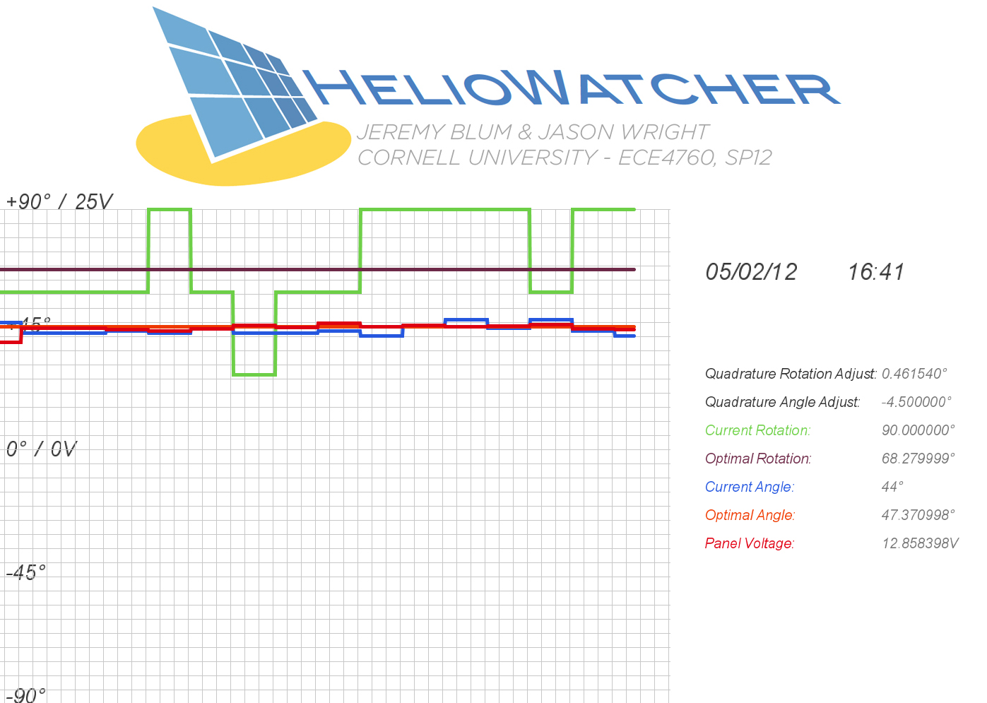
When in automatic logging mode, the HelioWatcher connects to a desktop application built in the “Processing” programming language. The MightyBoard implements a serial to USB conversion that allows the panel to easily be hooked up to a host computer via an ordinary USB connection. The processing script initiates automatic updates from the panel by sending a “data” command at boot. Following receiving this command, the HelioWatcher will automatically send updated status information to the processing script once every minute. This data, obtained from the GPS, accelerometer, quadrature, magnetometer, and some optimization functions includes the date, the time, the calculated optimal rotation and angle values, the current rotation and angle values, the panel voltage, and the quadrature rotation and angle adjustment values.
The application buffers until it finds a semicolon, marking the end of a data string, and explodes the contents of the string into an array of the above mentioned values based on comma delimiters. A real-time graph is generated to show the how these values change over time (see screenshot above), and the current values are printed to the display as well. This visualization makes it easy to correlate solar intensity (proportional to the voltage) to the orientation of the panel. In addition to displaying real-time data, the processing application also generated a Comma-Seperated-Value (CSV) value upon each run. As the application gets new data from the HelioWatcher, the previously created log file is appended with all the new data, and timestamped appropriately. This makes long-term data analysis extremely easy.
Results
Speed of Execution
The system is intentionally designed to move slowly, over the course of a single day, so this was not a concern. The stepper motors are run at low speed to maximize traction and to prevent slippage, since all the actuating devices were hand-designed. The code itself executes without significant delay.
Accuracy of Movement
The algorithms used provide accurate optimum positioning for the solar panel, given adequate calibration of the sensitivity to quadrature error-correction. However, accuracy of movement was limited by the switch from compass-based orientation to the “screw” method. Because we had a limited number of screws, the rotational movement has only 30-degree precision, which is not very accurate. In addition, the accelerometer’s values are slightly altered by temperature, which we considered accounting for using thermocouples, but did not have time to implement. We also struggled to precisely implement rotational movement, as the weight of the solar panel puts significant stress on the stepper motor and the 3D-printed wheel.
Safety
Solar panels guarantee that there are some safety concerns, but our project does not uniquely increase the risk of an accident. Users of the HelioWatcher should make sure that combustible material does not come into direct contact with the solar panel for extended periods of time, as this can cause fires. Users should also take care not to short the solar panel to ground. Because the HelioWatcher has moving parts, standard safety precautions should be taken — in particular, hands and feet should be kept away from the car jack as they could be injured if the jack clamps down. Small children and immature Cornell students should not be allowed to play on the rotating platform.
Interference
Our system is susceptible to magnetic field influence, which would adversely affect the magnetometer readings used for rotational angle measurement. The accelerometer readings are also susceptible to temperature variations. It’s also possible to interfere with our GPS reading using signal jamming or spoofing. The HelioWatcher does not generate any adverse interference.
Usability
Our system is usable by virtually everyone, as the user interface can by displayed or spoken with the addition of accessibility software.
Conclusions
The HelioWatcher largely met our expectations and proved to be a viable system for improving the efficiency of power generation using solar panels. However, we were disappointed that we were not able to include reliable compass data, and that we had to scrap the charge control circuitry part of our project proposal because we did not have the proper relays in time. We also intended to allow the user to log data to an SD card, which we were not able to get working in time. If we were to do this project again, we would work to implement these features earlier
Applicable Standards
The HelioWatcher adheres strictly to the RS232 communication standard, and although it does not send commands to GPS satellites, the module we used to implement the GPS protocol adheres to NMEA standards for GPS communication.
Intellectual Property
We used code in the public domain, explained earlier in this report and detailed below. We are not reverse engineering a design, and are not violating patents due to the non-commercial nature of our project. As solar trackers are not a new invention, we do not believe there are patent opportunities for the HelioWatcher. We do not intend to publish the HelioWatcher in an academic journal, but will share our ideas and experiences online and publicize the project.
Ethical Considerations
As electrical engineers, we strove to uphold the IEEE Code of Ethics at all times when working on the HelioWatcher. In particular, we made sure to maintain a safe working environment in the public spaces we used to develop the HelioWatcher, and produced a design that we felt would not have adverse impact on society as a whole. We did not discriminate on the basis of race, religion, gender, disability, age, or national origin while working on the HelioWatcher. We worked cooperatively with fellow ECE 4760 classmates for the benefit of the Cornell ECE community as a whole and did not disenfranchise or adversely affect the educational experience or professional development of our peers. For example, we open shared ideas for projects with fellow students and gave technical advice only where appropriate and called for, in accordance with the Cornell Code of Academic Conduct and the IEEE Code of Ethics. To the best of our knowledge, we have not misrepresented any of the background technical information surrounding our projects, and we certainly have not falsified data or experiences in developing the HelioWatcher. While this project was done to fulfill our obligations to Prof. Land and the ECE 4760 curriculum, the IEEE standards provide a valuable framework to apply our experience in project development to the ECE community as a whole.
Legal Considerations
To the best of the knowledge, there are no legal considerations surrounding our project. The HelioWatcher and its development are in accordance with all relevant laws & statutes.
Appendix A: Commented program listing
All source code is available on GitHub.

Appendix B: Schematics and 3D-Printed Part Designs
The schematics for the MightyBoard can be downloaded from Thingiverse, MakerBot’s object-sharing repository:
The MightyBoard Page on Thingiverse, Direct Link to Eagle SCH File, Direct Link to Schematic PDF
The System-Level Schematics of the HelioWatcher can be downloaded here:
HelioWatcher Eagle SCH File, HelioWatcher Schematic PDF
We also created a small Eagle Library for the System components (Schematics only, not footprints). It can be downloaded here.
All the 3D Printed part designs can be downloaded from Thingiverse. They have all been successfully printed on the MakerBot Replicator 3D Printer.
Appendix C: Bill of Materials
| Quantity | Part | Source | Total Cost |
| 1 | Solar Panel | Courtesy of Bruce Land | $0.00 |
| 1 | MakerBot MightyBoard | Previously Designed & Owned by Jeremy | $0.00 |
| 2 | NEMA17 Stepper Motor | Previously Owned | $0.00 |
| 1 | Car Jack | Previously Owned | $0.00 |
| 1 | 12″ Lazy Susan | Lowes | $9.26 |
| 2 | 2’x2′ Plywood Board | Lowes | $15.90 |
| 1 | 3-Axis Magnetometer | Sparkfun Electronics | $15.95 |
| 2 | Door Hinge + Screws | Lowes | $5.16 |
| 4 | Quadrature LEDs | Previously Owned | $0.00 |
| 4 | 330 ohm Resistors (for Quadrature LEDs) | Previously Owned | $0.00 |
| 2 | Wingnuts for Securing Car Jack | Lowes | $1.60 |
| 10 | Wave/Spring Washers for Securing Rotation Stepper | Lowes | $0.56 |
| 20 | Wood Screws for Assembling Base | Previously Owned by Jeremy | $0.00 |
| 2 | 3D Printed Top/Bottom Quadrature LED Holders | Printed on Jeremy’s MakerBot using Free Plastic | $0.00 |
| 2 | 3D Printed Left/Right Quadrature LED Holders | Printed on Jeremy’s MakerBot using Free Plastic | $0.00 |
| 1 | 3D Printed Elevation Jack Bracket | Printed on Jeremy’s MakerBot using Free Plastic | $0.00 |
| 1 | 3D Printed Elevation Jack Collar | Printed on Jeremy’s MakerBot using Free Plastic | $0.00 |
| 1 | 3D Printed Rotation Stepper Bracket | Printed on Jeremy’s MakerBot using Free Plastic | $0.00 |
| 1 | 3D Printed Rotation Wheel | Printed on Jeremy’s MakerBot using Free Plastic | $0.00 |
| 3 | 3D Printed GPS,Antenna, and Magnetometer Covers | Printed on Jeremy’s MakerBot using Free Plastic | $0.00 |
| 1 | Libelium GPS Module | Sent to Jeremy for free to Review | $0.00 |
| 100 ft | Assorted Stranded and Solid Wire + Jumper cables | Previously Owned | $0.00 |
| 1 | 2×4 Lumber | Lowes | $3.27 |
| 1 | 20k Resistor for Solar Panel Voltage Divider | Previously Owned | $0.00 |
| 3 | 10k Resistors for Solar Panel Voltage Divider | Previously Owned | $0.00 |
| 1 | 0.1uF Capacitor for Solar Panel Voltage Divider Filter | Previously Owned | $0.00 |
| 1 | 12VDC Wall Wart for MightyBoard | Previously Owned | $0.00 |
| Lots | Heatshrink Tubing | Previously Owned | $0.00 |
| 2 | BotStep17 Stepper Motor Drivers | Previously Owned | $0.00 |
| 2 | Locking Nylon Nuts | Lowes | $0.34 |
| 2 | Hex Cap Bolts for Securing Panel to Hinges | Lowes | $0.40 |
| 1 | 3D Analog Accelerometer | Previously Owned | $0.00 |
| TOTAL | $52.44 |
Appendix D: Distribution of work
- System-level software design
- Circuit design for quadrature light detection
- Programming of stepper motor library functions
- Programming of ADC accelerometer values
- Measurement and calibration of panel alignment functions
- Interface with UART GPS module
- Implementing 3rd party library for parsing NMEA GPS sentences
- Programming of debug/manual operation mode
- Development of magnetometer “stud-finder” mode
- Computer Aided Design & 3D Printing of Hardware components including car jack bracket/collar, rotation wheel, component covers and quadrature mounts
- Woodworking and Assembly of Solar Panel platform & movement mechanisms
- Schematic Development & System-level hardware design; design of the MightyBoard MotherBoard (while previously working at MakerBot)
- Integration of Solar Positioning Optimization Algorithm based on NREL Research Paper
- Programming of Software I2C Stepper Driver Voltage References
- Programming and Algorithm Development of Hardware I2C Magnetometer (in original compass mode)
Appendix E: Reference Listing
- Solar Position Algorithm for Solar Radiation Applications (pdf) via NREL Website
- NMEA GPS Syntax Reference Page
- Libelium GPS Module Tutorial
- Astronomical Coordinates Information Page from Case Western Reserve University
- HMC588L Compass Module Reference Code from “Elia’s electronics blog”
- Jeremy’s Previously Designed Weather Station Monitoring Processing Code
- MakerBot MightyBoard Schematics
- Procyon AVRLib Documentation
- Sun Position Approximation Script by Professor Goldstein of Providence College
- Sun Position AVR Code based on above Sun Position Script via AVRFreaks.com
- Atmega1280 Datasheet (pdf)
- Vincotech GPS Module Datasheet (pdf)
- Accelerometer Datasheet (pdf)
- Magnetometer Datasheet (pdf)
- MCP4018 Digital I2C Pot Datasheet (pdf)
- Writing to CSV from Processing
- Cornell’s ECE4760 Labs 1-4 Reference Pages
Acknowledgements
Thanks to Bruce Land and all the ECE 4760 TAs, in particular Joe Montanino & Pavel Vasilev, for their instruction and guidance this semester.
Thanks to Pascal Stang, whose AVRlib suite made this project substantially easier.
Thanks in particular to Brian Schiffer & Sima Mitra, who continually offered advice and troubleshooting help during this project.
Thanks to Allie Riggs for designing our logo.

